
EVIDENCE-LED MATERIAL CHOICE
Where the plywood structure makes sense — and where steel remains essential
The current HARDY architecture is a load-sharing plywood box: 18–21 mm panels, plywood stiffening ribs, 3 mm steel angle connectors, industrial bearings and local metal interfaces. The relevant comparison is therefore not “wood sheet versus steel sheet”, but two complete load paths and their mission consequences.
Use the plywood box where geometry, low mass, repairability and serial CNC production create value. Use steel at bearings, shafts, motor mounts, towing points, impact zones and every interface whose load or temperature requires it.
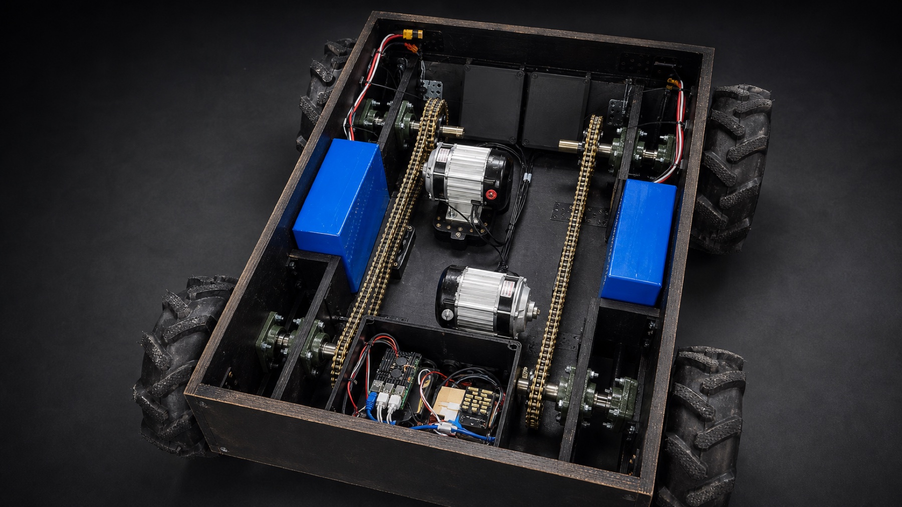
ACTUAL HARDY ARCHITECTURE
Plywood load-bearing box.Two drive circuits.
This is not plywood cladding over a hidden steel frame. Panels and ribs form the load path; steel is used locally where torque, bearing load or wear requires it.
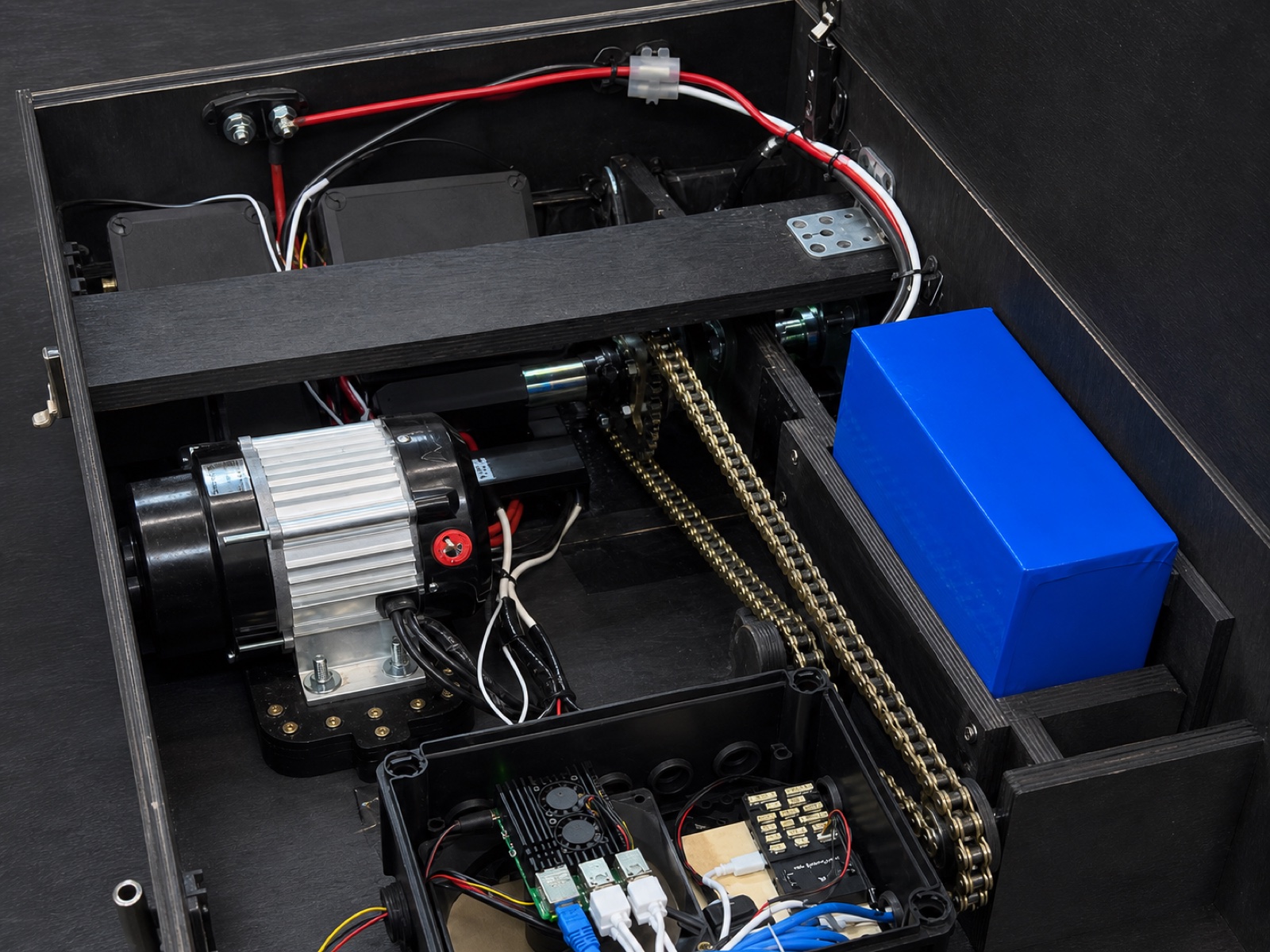
- The floor, sidewalls and transverse ribs form a closed coated-plywood box.
- Two gearmotors create independent left and right drive circuits.
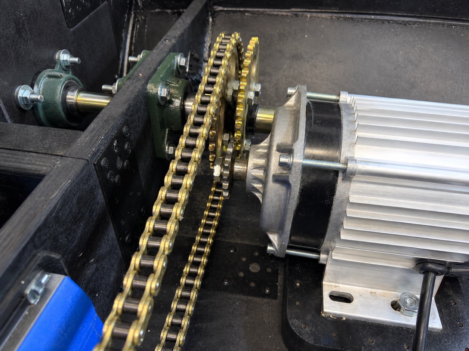
- Chains transfer torque to the front and rear shafts through industrial bearing units.
- Steel remains at shafts, sprockets, bearings, mounts, fasteners and 3 mm angle connectors; batteries and service electronics are arranged symmetrically.

02 / Interactive model
Compare your shell parameters
The plywood side includes panels, plywood ribs, 30 × 30 × 3 mm steel angles and fasteners. The steel side is intentionally conservative: it includes only a bare shell of equal area, without its own ribs, brackets, welds or corrosion coating.
Screening calculation only. It excludes openings, joints, stress concentrations, fatigue, impact, moisture cycles and the steel shell’s required reinforcements. Production design requires drawings, load cases, FEA/coupon tests and a full-platform acceptance programme.
03 / Physics and geometry
The numbers explain why geometry matters
| Property | Birch plywood 18–21 mm | Structural steel 6–8 mm | What it means for the UGV |
|---|---|---|---|
| Density | ≈700 kg/m³ | 7,850 kg/m³ | Panel mass is the largest immediate difference. |
| Mass per m² | 12.6 / 14.7 kg | 47.1 / 62.8 kg | Lower shell mass can become payload, battery reserve or lower ground pressure. |
| Elastic modulus | 7.45–10.05 GPa (18 mm); 7.64–9.86 GPa (21 mm) | 210 GPa | Steel is much stiffer as a material; plywood closes part of the panel-level gap through thickness and directional lay-up. |
| Panel screening E·t³ | 43–59 kN·m (18 mm); 71–91 kN·m (21 mm) | 45 kN·m (6 mm); 108 kN·m (8 mm) | The figures are of the same order for some pairings, but openings, joints, ribs and orthotropy decide the real body. |
| Through-thickness conductivity | 0.147–0.175 W/(m·K) | 48 W/(m·K) | Plywood slows heat flow; this changes transient surface temperature, not guaranteed detectability. |
| Environmental weakness | Moisture at exposed edges; combustible | Corrosion; rapid heat conduction | Both systems need deliberate protection, inspection and repair criteria. |
Panel mass follows density, area and thickness.
Thickness enters bending stiffness to the third power; the full plate equation also needs Poisson/coupling terms.
Closed boxes and ribs move material away from the neutral axis, increasing structural stiffness.
Lower mass reduces the ideal rolling-work component, but real range remains a field-test result.
DESIGN CONVERSION
The material is valuable because the architecture uses it deliberately
The structure gains panel depth and sectional geometry while keeping a large mass advantage.
The small internal-volume penalty supports screw/insert engagement, cable routing and replaceable local details.
Coating, sealed edges, drainage and replaceable panels create a visible maintenance regime instead of hidden corrosion.
Low conductivity slows heat transfer; batteries, power electronics and hot interfaces still require metal shields, spacing, detection and suppression appropriate to the hazard.
The base shell avoids the weight of unverified pseudo-armour; tested inserts, shields or sacrificial modules can be localised to the threat and mission.
Antenna placement is less constrained by a continuous metal enclosure, while deliberate grounding and EMI shields remain local engineering features.
04 / Thermal imaging
Same heat sources. Different surface pattern.
With the same matte coating, both bodies have similar surface emissivity. The difference begins underneath: plywood slows heat transfer through the wall, while a continuous steel shell conducts and spreads heat across a larger area more quickly.
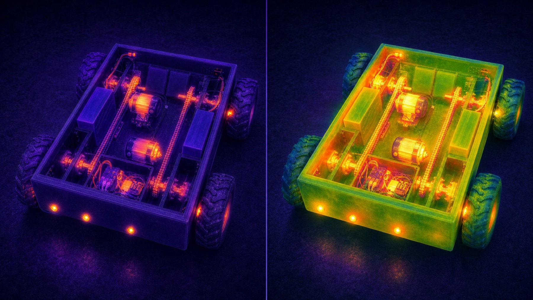
Comparative thermal model with identical source layout: localised pattern in plywood and wider heat spreading through steel.
Low through-thickness conductivity delays body-wide warming. Motors, bearings and cable entries remain visible as separate local zones.
A continuous metal shell carries heat away from its sources quickly, so a larger share of the panel can enter the thermal image during operation.
Bearing interfaces, motor mounts, electronics and ventilation still determine the strongest contrasts. Their layout, isolation and duty cycle must be engineered together.
05 / Impact, blast and protection limits
The same event creates a different damage geometry
The key difference is not “indestructible versus fragile”. It is where the structure accepts energy, how far permanent deformation propagates and what must be replaced before the platform returns to service.
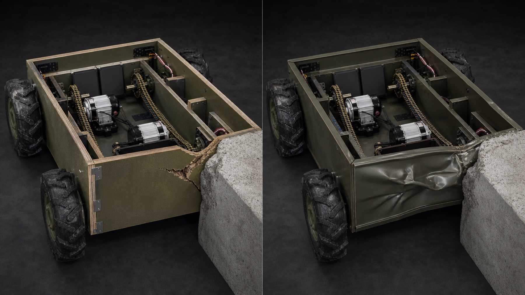
SCENARIO 01 / COLLISION
A rigid obstacle loads one corner of the box
Collision energy grows with mass and the square of speed. The body architecture decides whether that energy remains near the contact zone or distorts a larger connected shell.
- local edge crushing, cracking and veneer delamination;
- joint slip or fastener pull-out can dissipate part of the event;
- the affected panel, corner and fasteners define a replaceable repair zone.
- local yielding produces a dent, folds and inward intrusion;
- permanent deformation can travel across a continuous sheet and into the seam;
- restoring geometry commonly requires straightening, cutting and welding.
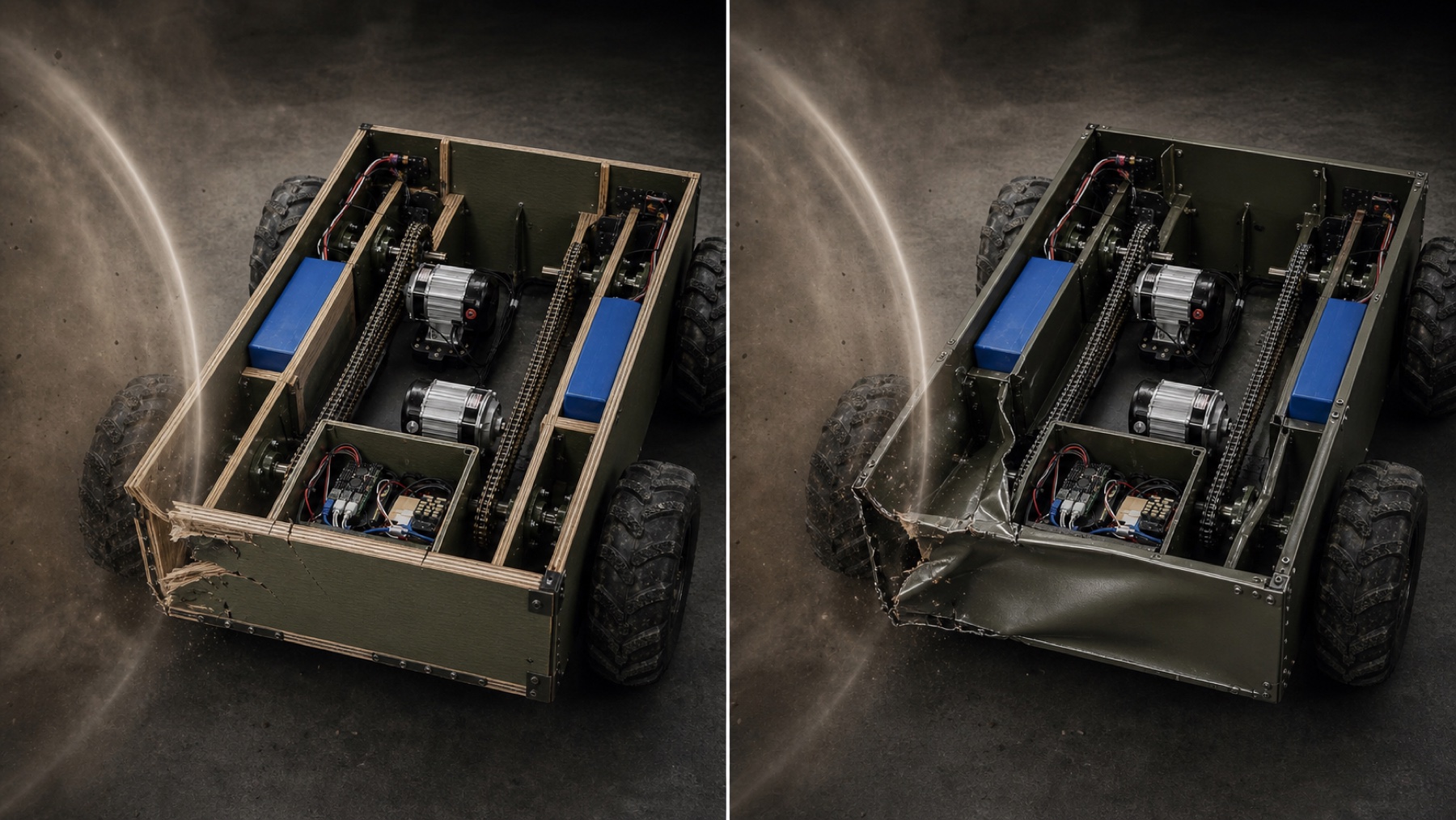
SCENARIO 02 / EXTERNAL BLAST IMPULSE
A short pressure pulse loads a wide surface
Response depends on the full pressure–time history, distance, angle, supports, openings and joints. Under the same hypothetical impulse, plywood and steel usually leave different geometric signatures.
- local rupture, delamination and short cracks near the loaded edge;
- joint opening and sacrificial fastener release limit transfer into adjacent panels;
- damage is visible and can be isolated as a panel-and-joint replacement.
- the sheet forms a broad permanent dish with fold lines;
- buckling or tearing can concentrate at seams and supports;
- distortion may alter clearances and alignment beyond the visibly torn point.
Speed dominates the energy entering the contact corner; joint and panel geometry govern the resulting damage path.
Pressure integrated over time drives dynamic response; peak pressure alone is not enough to predict the final shape.
A bounded panel, rib, angle and fastener set can be inspected and replaced from the controlled CNC file.
Connected permanent distortion requires checking datums, seams and component clearances before local cosmetic repair.
PROTECTION BOUNDARY
Damage behaviour is not a protection rating
These scenarios explain probable deformation paths, not guaranteed survival. Exact outcomes require the production lay-up, joints and supports to be tested against a defined speed or pressure–impulse case. The current 18–21 mm plywood box and ordinary 6–8 mm S235/S355 shell therefore remain structural systems without a published ballistic or blast-protection class.
PLYWOOD BOX IS RATIONAL WHEN
- mass, payload and ground pressure dominate;
- rapid CNC repetition and local repair matter;
- the body is a closed ribbed structure rather than an unsupported flat plate;
- edges, joints and coating are controlled.
STEEL REMAINS ESSENTIAL WHEN
- loads are concentrated at bearings, shafts, motors or towing points;
- high temperature, abrasion or repeated local impact is expected;
- a conductive ground or EMI enclosure is deliberately required;
- verified ballistic protection is a requirement.
06 / Sources and input data
Primary data used in the model
- ArcelorMittal · Heavy steel plates EPD — ρ 7,850 kg/m³, E 210 GPa, λ 48 W/(m·K), structural grades and yield-strength range.
- Koskisen · Birch plywood Declaration of Performance — directional bending strength and elastic modulus for 18 and 21 mm panels.
- Koskisen · Handbook of Finnish Plywood — density basis, moisture, thermal conductivity, fire behaviour and design factors.
- FLIR · How emissivity affects thermal imaging — emissivity of polished/oxidised metal and flat paint, reflection and apparent temperature.
- FLIR · Thermography measurement parameters — surface temperature, distance, ambient temperature and emissivity.
- US National Institute of Justice · NIJ 0101.07 — example of threat-specific, conditioned laboratory ballistic testing; not used as a vehicle rating.
- USDA Forest Products Laboratory · Wood Handbook, Chapter 8 — fastener withdrawal, lateral resistance and connection behaviour in wood structures.
- USDA Forest Products Laboratory · Wood Handbook, Chapter 11 — plywood and wood-based composite construction.
- US DoD · UFC 3-340-02 — pressure–impulse loading and dynamic structural response; used only as the mechanics basis for the qualitative blast scenario.
- AV Metal Group · public S235JR price list and Meblyar · plywood price list dated 16 June 2026 — calculator price snapshot.
Results depend on the dimensions, material properties and prices entered above. This is a comparative calculation, not a manufacturing quotation or evidence of a finished platform's structural performance.